I usually don’t do much with the figures…..very little interest. I have a fairly decent number of pilots……..more if one saw the figures I have from ship kits. I haven’t done too many dioramas either. This kit comes with three figures, all standing…….the pilot and two mechanics. I decided to paint them….something I haven’t got much in the way of experience with. I figured I’d better bone up on it, since I have the Budweiser Clydesdale wagon and a stagecoach model to do…each comes with horses and figures.
Earlier, I painted the bases, boots and the main dress of them…….now to do the faces and fleshy parts. This is where they become tricky…..although, I did do Batman!
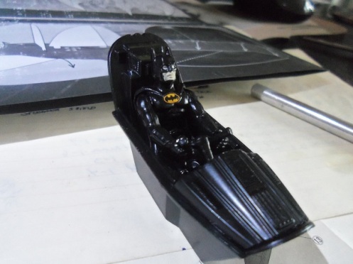
…..not too tough a pill to take……….no ruby red lips………….all business…..and definitely not kissable! LOL! Although, in the TV version of Batman, Catwoman was madly in love with ’em 😉 …….tried many time to seduce him. but……this is a family show 😉
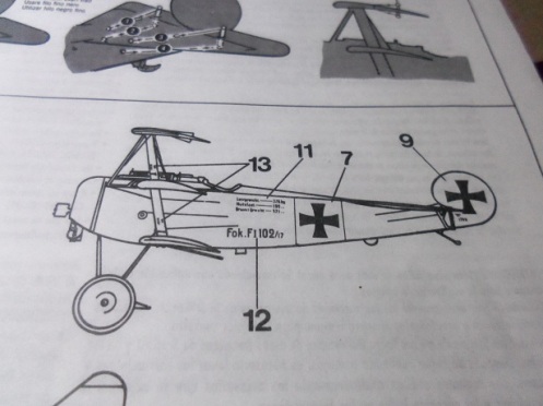
So………I did the pilot. Ltn. Carl Jacobs…front and center! {I think he’s missing something}
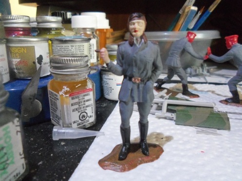
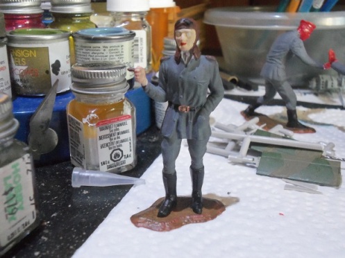
I have the Lifecolor paint set…….but it is an acrylic set……..I used enamels to paint him. He needs a little shading….there are tutorials on YouTube that can give some pointers.
I also added to the mechanics…….they need shading too……..
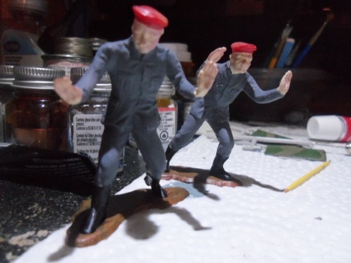
Not much left to do with this project now………more to come.
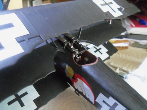
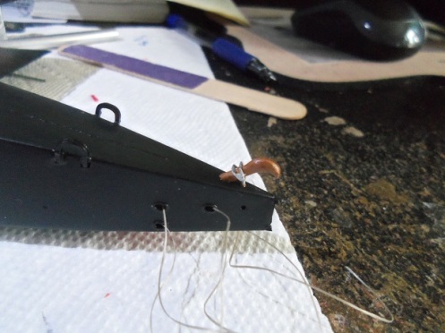
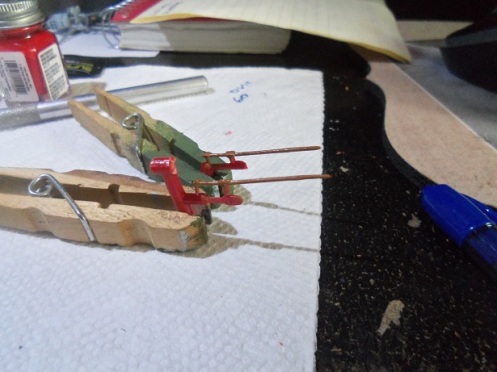
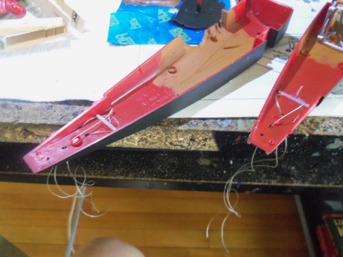
I gave the control cable levers a few days to dry. Metallic enamel paints do not cure like other paints of this type does. They can remain tacky if used too soon…..one reason why I avoid painting planes in these colors. I always seem to get annoying fingerprints and weird marks. The levers were cemented in place, in the ailerons of the top wing.
The cables were then cemented to the levers and trimmed off.
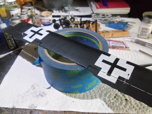
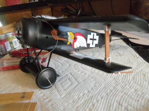
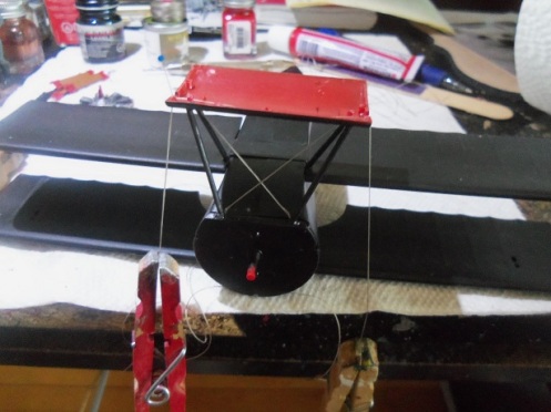
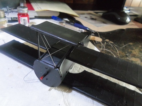
Once done, the wing was then cemented in place on the model. Masking tape was used to align it. I gave it a good amount of time to set, before the cabane struts were added.
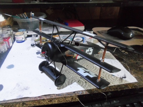

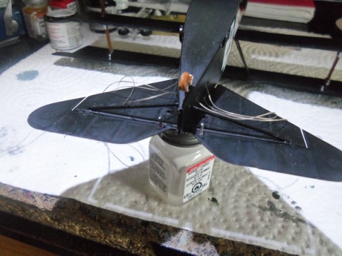
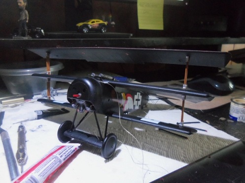
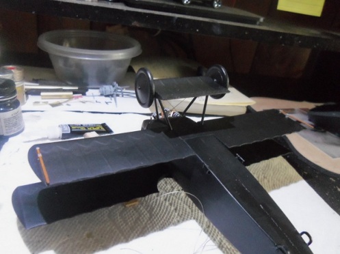
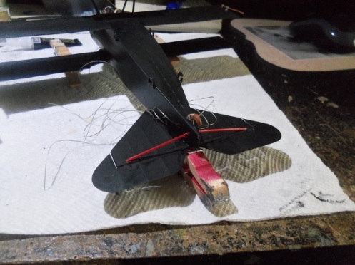
This really changed the looks of the model. It was given more time to dry, and when it was ready, it was set upside down, to rig the cables to the underside of the top wing.
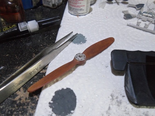
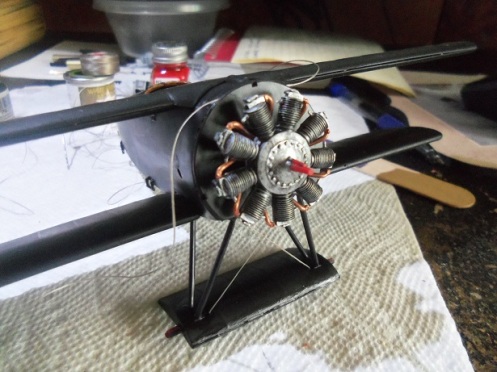
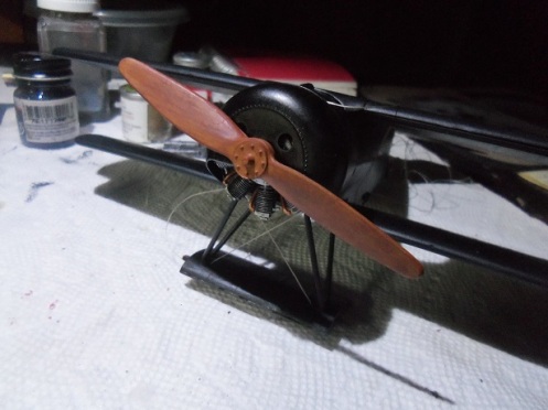
The detail painting on the prop was finished at this time.
The prop was then cemented on the shaft, which is keyed, acting as a guide. I don’t know why, but it fit on quite well…..as with the actual aircraft, the engine rotates along with the prop. I moved it so show that it is able to move freely.
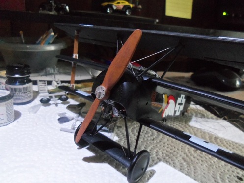
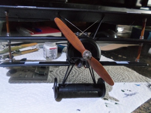
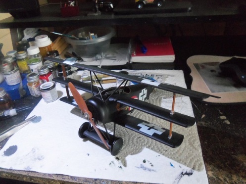
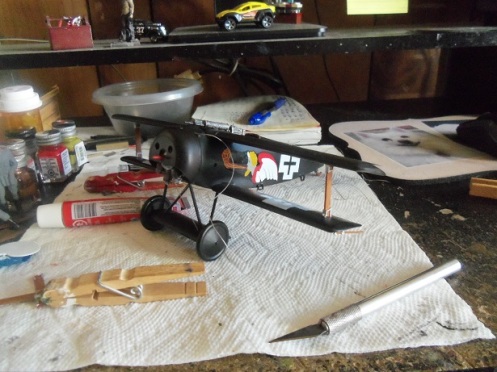
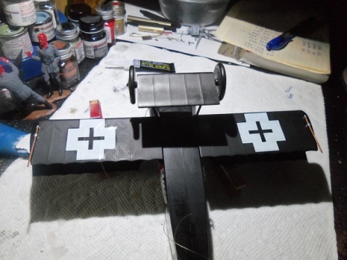
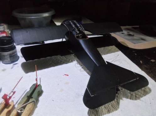
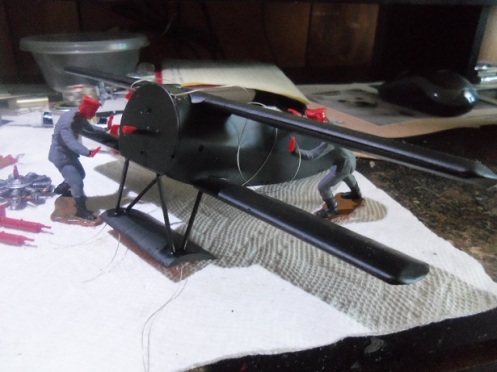
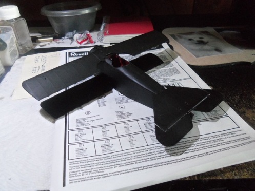
….a picture of the state of the model, as it is now…….
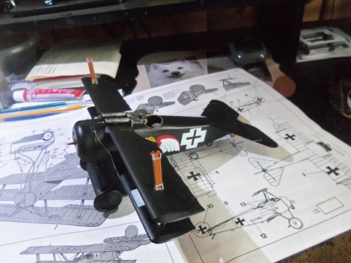
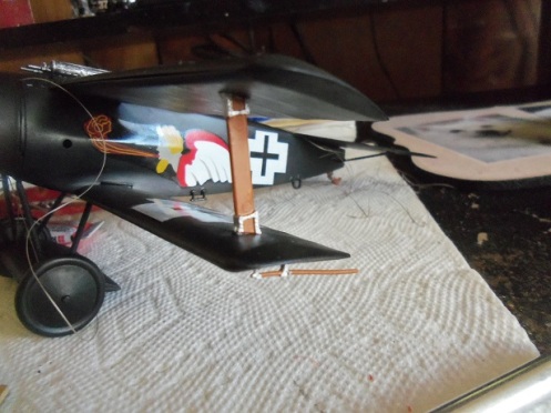
The stabilizer elevators were rigged next. The control levers were cemented in place and allowed time to dry before the cables were added.
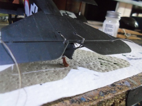
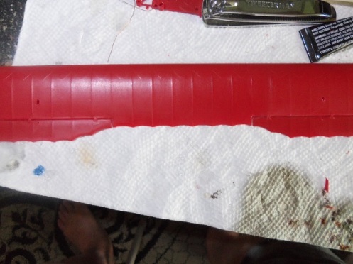
The only part left to add is the rudder. I still need to paint it……..and for that, I will use the airbrush. It’s very hard to use a brush to paint white……I hate it. It leaves too many stroke lines and the ghosting is terrible….especially in this case, where the rudder is red plastic. More soon!
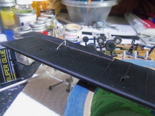
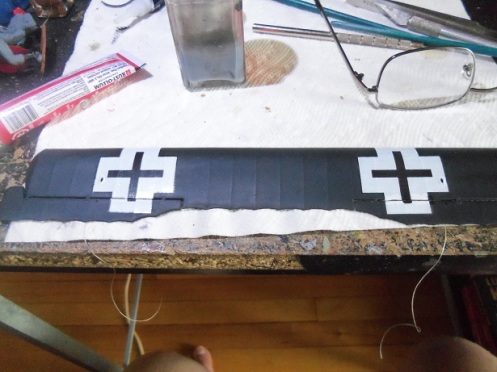
Continuing on from the last session, before the top wing can be assembled, the control cables need to be cemented to the inside surface of the upper half. The control levers were painted with flat steel and set aside to dry. Since I am using decals from the Roden kit, I will need to cut the decals for the top wing, so they will fit on the wing and the ailerons. The decals that came with the kit have these two decals already separated, but I can’t use them since on Jacob’s plane, the insignias are different. Older model decals were thicker…..I’m fairly used to them……easy to cut or make alterations to them. More modern decals in today’s kits are a lot thinner……allows them to look more authentic and realistic. To cut them proved to be a bit daunting because of the thickness aspect; it made them prone to ripping and tearing……even with a new {sharp} blade. There are a couple of imperfections, but I will touch them up with paint, which will make them look better. The control cabling was cemented on the inner surface, and then thee decals were added.
From here, the control cables were threaded through the access holes. Just for giggles, I put the bottom half on the model…….just to see what the spacing looked like. The interplane struts are not cemented in place……says a lot about the fit of these parts.
The top wing was assembled at this point……
The interplane struts were cemented to the middle wing……..
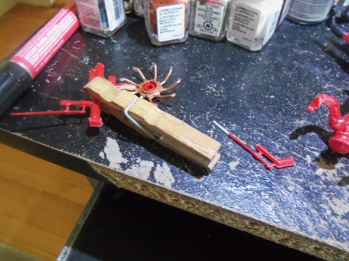
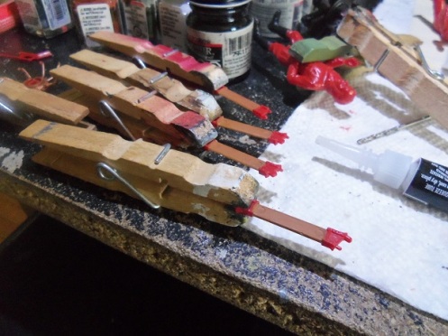
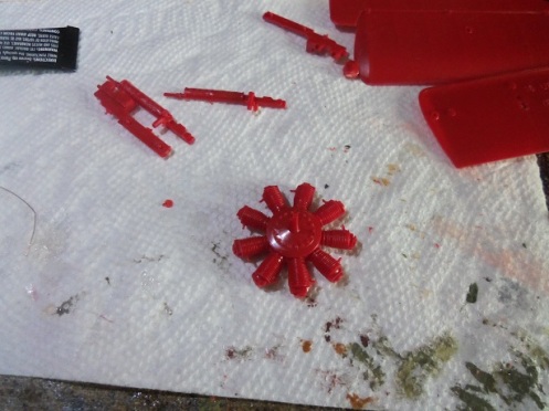
…….and the control levers were trimmed and cleaned up for painting.
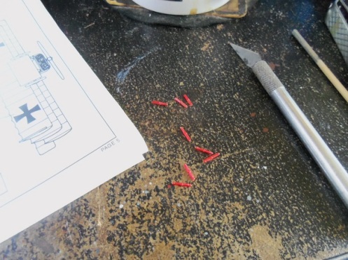
There are a few more than are needed……I guess…..in the event that some get damaged for some reason. More to come……….
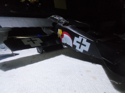
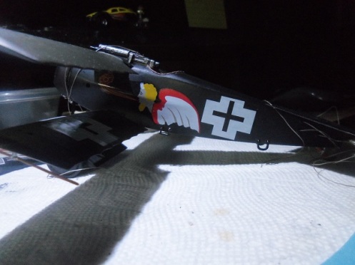
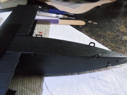
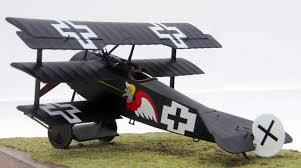
I got home from work the other day. While sitting at my desk, I used the natural sunlight to snap a few more pictures of the Dr 1.
The interplane struts are ready to add to the model. The lower pair were cemented in place.
The Revell rigging of this model does fall short when it comes to the cables for the top wing. There are no molded holes to rig them, rather they are run through holes in the cabane strut upper roots and cemented there. It would be hard to copy the detail that the kit has for the molded holes, so I won’t try to alter this. I’d probably make a mess out of it. I started to look at the top wing assembly……likely what I will do next.
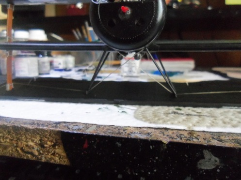
This session was broken into two parts, since on Friday, we run our errands. The wing skids and the tires were added to the plane.

The stabilizer truss rods were added too, later painted in flat black.
We went on our errands……..I didn’t come back to her, until after supper. I thought it might be best to do the bulk of the decaling now.
There is a matching set of insignias on the topside of the bottom wing…..why, the info on the plane and its pilot didn’t say. The fuselage decals were added as well. I wish I had moved this to better lighting…..I’ll have pictures later on.
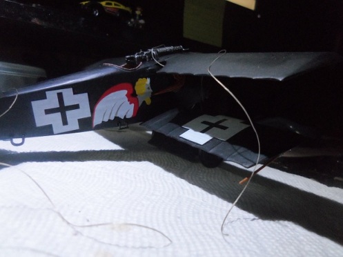
This decal split in two…….right down the middle. It didn’t take too much to align it.
The cabane struts, the rudder {including paint and decaling}, the interplane struts, and the top wing, are all that is left. Still more to come……..
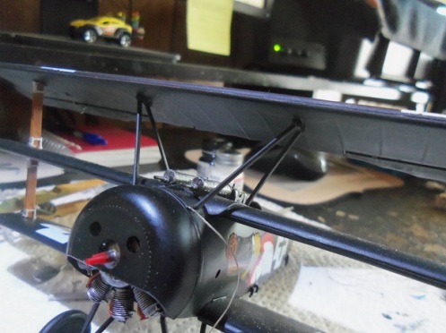
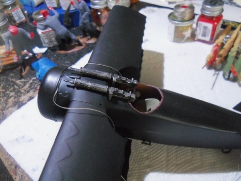
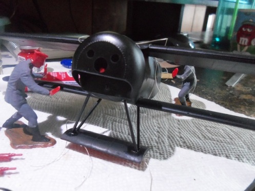
In this short session, the machine guns were added. The cowl and engine were also added, but not before trimming down the locator pins that align it in its proper place.
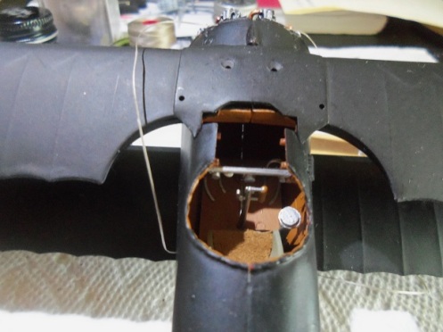
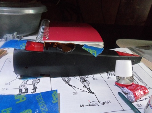
The padding around the cockpit was also painted. It looks a bit scant……..I was going to remove it and dub in a ring of leather. I didn’t want to chance ruining the model, so I left it as is.
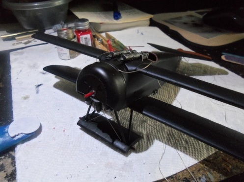
The Stabilizer deck was also added.
It can also be seen that I finished painting the skids, accenting the brackets. I did a bit more on the interplane struts too.
More to come……….
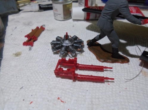
More has been done on this model…….starting with the figures. I don’t really do that much with them, even the pilots. I have a stash growing in my spare parts box, as we speak. Even with model ships…….I have sprues of them. These I decided to paint and build on…….they’re even beginning to help me. I kinda got ahead of myself here…..the bottom wing, the middle wing, and the landing gear has been cemented in place on the model. so has the firewall, which needed the addition of rigging cables, top and bottom, to be installed.
The engine is assembled…….the guns are in the beginning stages, and the interplane struts are stacked after their initial paint. I heard that model Monkey has begun to offer aftermarket parts for 1:28 scale…..the machine guns look especially good.
the cowl was painted and dry fitted in place………it made me think. I have the ‘face’ decals…….I think they are 1:32 scale, but I’ll bet they will work. The only thing that holds me back, is the fact that Jacob’s plane didn’t have it.
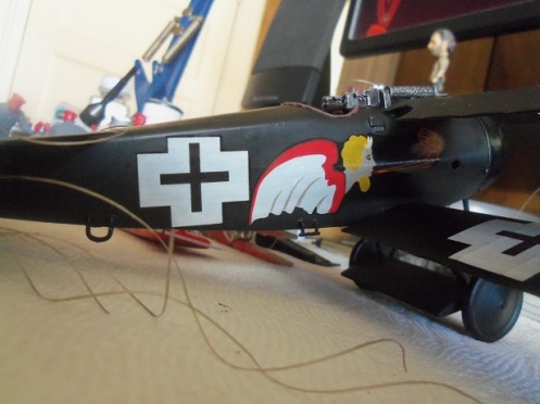
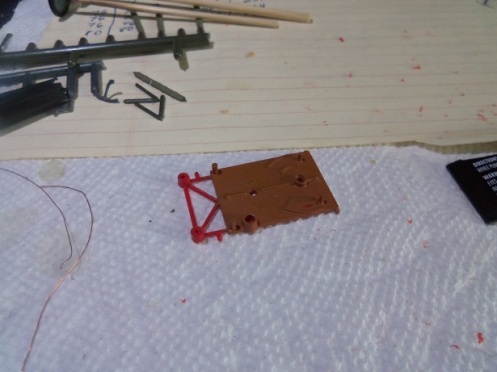
With the landing gear installed, the truss cables were rigged by threading them through the holes in the gear platform. They were then tied and dabbed with Ca to prevent them from coming apart.
The grab handles and steps were added next. According to the diagram in the Roden instructions, they were black…….and so they are painted……
The bottom half of the landing gear platform was added to the model, once the cement on the thread was dry and trimmed. The truss cables are nice ‘n taut.
The engine was dry fitted in place……it slides onto the pin in the center of the firewall, and will not be cemented. The prop pin is ‘keyed’, so the prop and engine will be able to spin. If all goes well, this will be the result.
Once painted, the tail gear was added…….
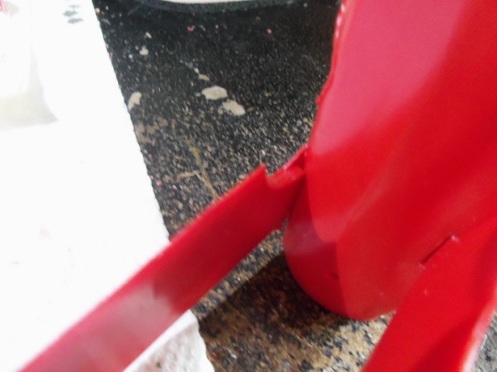
I was a good boy……I gave the broken skid time to fully dry. It was trimmed to length and sanded to match the other one. They received their base color.
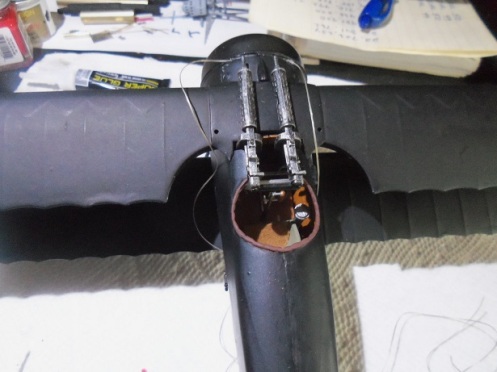
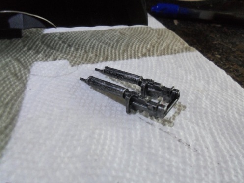
The machine guns got their paint, dry brushed with flat steel.
Looking in the cockpit, the four tabs and two locator holes on the fuselage bonnet, will affix the machine guns firmly……it’s the best set up I’ve seen yet. The cockpit itself is fairly detailed.
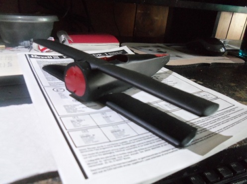
lastly, in this session, the prop was painted wood brown, dry brushed with a darker brown.
More to come………
I’ve gotten a bit further on the project. It’s been a lot more in the way of painting.
The figure’s bases and feet is their starting point. I’ve also done the base coat on the engine…..it will be dry brushed with aluminum when dry. A while ago, I received a bunch of paints from a friend…….he has a friend who’s brother passed away, who was an avid modeler. Some of the paints were too old, but the majority of them were still good……brands like White Ensign, Hunbrol, Monogram and Testors. I’m using these paints for the model….so far, it’s been a lot of stirring and shaking, but I’ve gotten good results. I’m happy……..it saves me money!
One of the wing skids had the tip broken off……..I have no idea where or when. I found a plastic dowel about the same diameter, and have been able to fix it. It will be sanded and cleaned up before painting.
The cockpit was assembled and cemented into one side of the fuselage. It was then sandwiched until dry, so the cockpit assembly can align with the opposite side.
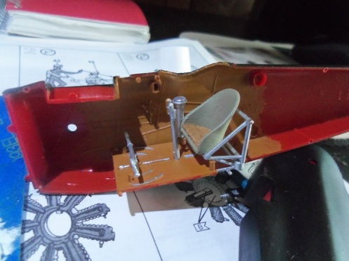
As I did with the Roden kit, the seat was lined with a piece of leather, cut to the shape of the bucket. There was an injection circle in the middle of it……this is a great way to get rid of it. There also was a half moon shaped piece of plastic among the loose parts, which I thought was the instrument panel. Later I found this not to be true, after seeing a bar that will span across the cockpit, with a few gauges on it. That will be installed when the fuselage is permanently cemented together.
Before the fuselage can be closed up, the control cables for the elevators and rudder need to be installed. They were glued down with CA, and I added a bar across them to insure they don’t come apart. The fuselage was finally assembled when I was sure that all this was dry enough.
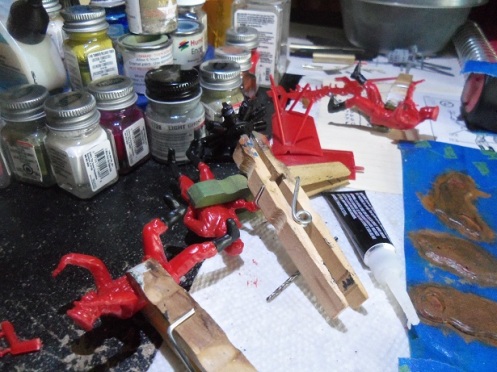
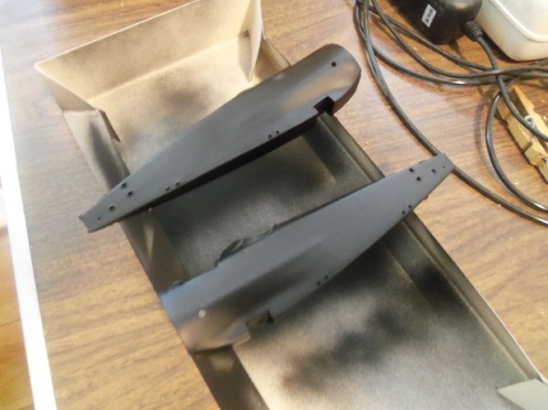
I think it’s one thing that the bulk of a plane is one color, but black is the most ‘cloaking’ of all the colors, in regards to detail. It will hide everything……….so, I’m going to do some accents here and there to break it up. Decaling will add more color. Parts like the interplane struts {pictured here} will be detailed out, separating the bracketing from the support. The cabane struts though will remain the scheme color – black. As I’ve seen with other early models, the tires were not painted black. Back in the early days of rubber, it was produced and used in its natural state……the black color we see today is the addition of a color additive. When this occurred in the evolution of rubber……I researched it, but can’t think of it at the moment. For this model though, I’ll leave them black…they are already painted.
There is more to come……..
I’ve given it the ‘defining’ moment……..painting has begun. It actually began during the last session…….the first part was painted.
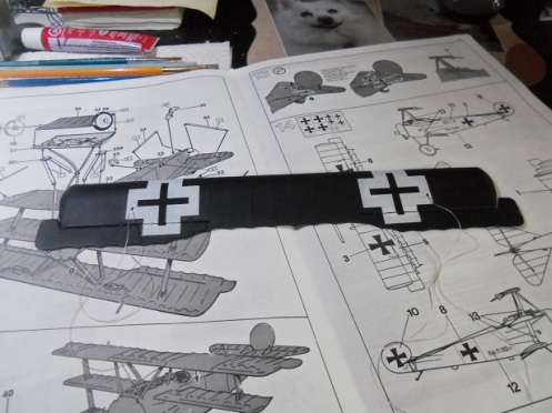
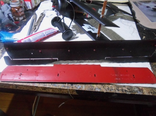
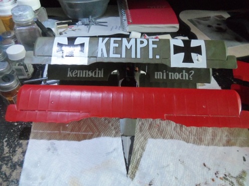
I wanted to make sure that I can use the decals from the Roden kit. I did a comparison alongside the Kempf model, so you can see the size difference.
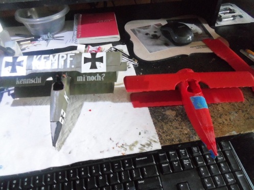
It appears fairly subtle…….the top wing as well.
The Roden kit does not have {or show} the control cable rigging…….I’ve drilled the holes and am installing it. The holes in the top wing of the Revell model shows the holes for this rigging. These models are large enough to possess this detail…….silly not to actually.
Note that the Roden kit has the single wing rib curvature. I thought I’d point that out.
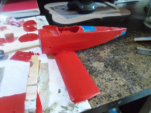
The decals for Ltn. Jacob’s plane were cut out and laid on the fuselage for fit. The good thing about this particular plane, is that it’s all black and won’t bear the plane ID number.
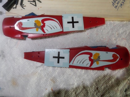
They look good…….the plane is a go!
The cockpit needs to be painted and assembled before the fuselage halves can be joined together. The fuselage was masked up…….all contact points for cement were masked as well, and the majority of the exterior was painted flat black.
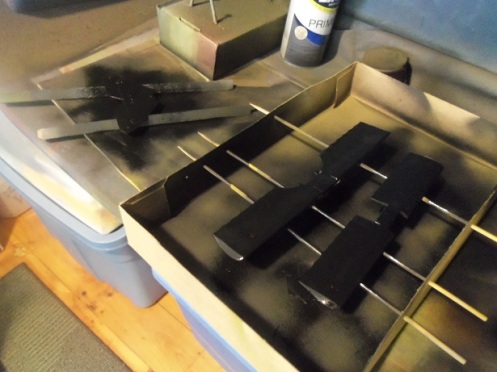
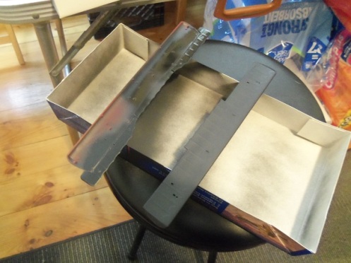
The paint went reasonably well. One minor fo-par was that I didn’t give the parts on the skewer rack long enough to cure and I flipped them over to paint the other sides. I was unhappy to see unsightly lines on them………had to paint them over again. I was working, so the parts had plenty of dry time. I don’t do much modeling during my work week. I did a dry fit of the fuselage and wings {minus the top wing}….happy with the way it looks!
Should be an interesting plane!
The next thing I did, was to assemble the main parts of the engine.
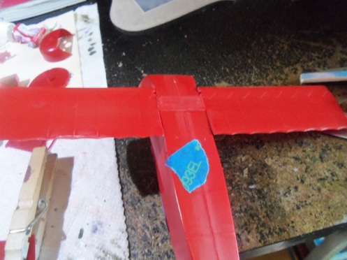
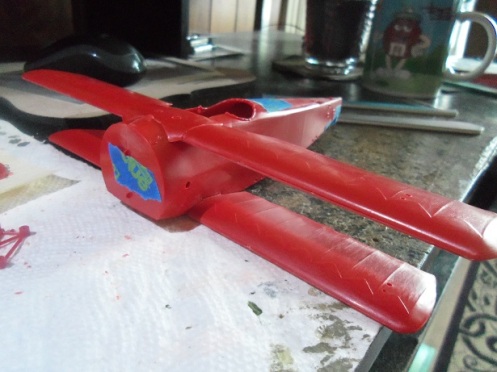
Since the bottom wing and the middle wing doesn’t include any rigging, they were also assembled. The paint scheme of the Jacob’s plane is not highly involved, only painted in one color, so they can be painted in their entirety. Dry fitting is the next process. The fuselage was taped together in order to fit the bottom and middle wing.
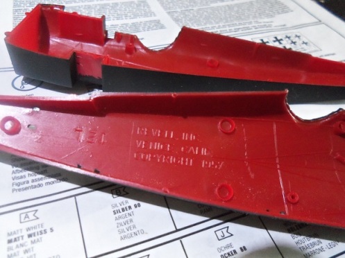
The wing root should fit flush in the slot….it will cut down on the amount of touch ups after everything is painted. I noticed that the mould date stamp is located on the root ‘bar’ of the bottom wing. Usually they can be found on the inner surface of the parts, but this one was on the outer surface {Revell 1981}……..I sanded it off. I did find this as rather odd, since the kit was produced and sold by Revell Germany. This kit is dated 1992…..instructions and decal sheet as well. Revell USA was sold to Hobbico some years back, leaving Germany it’s sole entity. Revell was still in business in 1981, so chances are, they are using the original moulds. The other thing that I found interesting, was on the inside surface of the port side half of the fuselage, is another Revell stamp: Revell Inc Venice Calif. copyright 1957. This suggests that the model was moulded with two different sets of moulds. I find this type of trivia interesting…..an example is how surprising it to find how many companies are using old Aurora moulds.
Moving on……….the middle wing was a bit of a challenge to fit. It didn’t want to fit flush in its slot. Any minor flashing along the edges of the slot was sanded to make it flat.
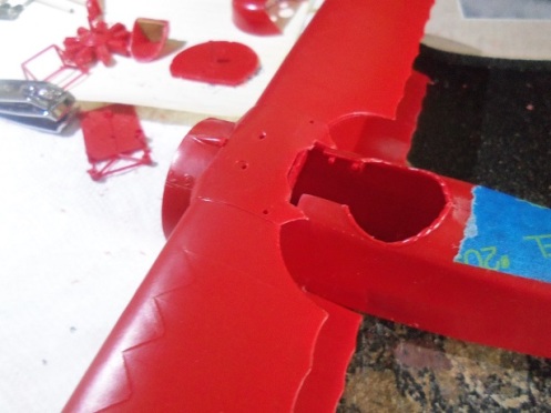
When I glue it down, some pressure will need to be applied to keep it flush until it dries. I do notice that there are voids under the fuselage bonnet, joining the middle wing, that I may need to fix.
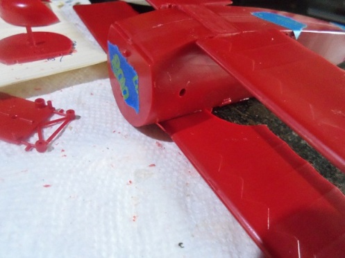
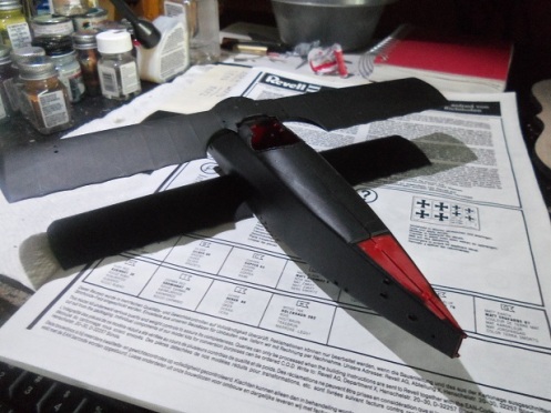
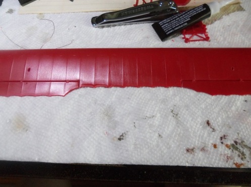
Filler might do well in these places……I’ll see what they look like after painting. It may tend to hide these areas {sometimes paint can help with situations like this}. Now we arrive to what I wanted to show in this update. As I see it, concerning the aileron issue, there is only one real option. I will make the port side look like the starboard side. I could go the other way around, but it’s a lot more work to add material, rather than subtract it. The aileron on the starboard side has the two wing rib curvature, and the port side has the single rib curvature. I’m going to make the port aileron look the same as the starboard side.
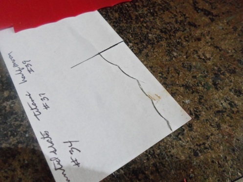
Taking a piece of paper, the right aileron was traced……I went a little further down the length of the aileron to use as a guide, since they are moulded to the wing.
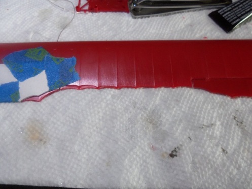
Once cut out, it was taped to the port side aileron, which exposed how much of the aileron needs to be removed.
With a pair of convex nail clippers {my ‘go to’ tools}, the excess material was clipped off and the edge sanded to finish shaping the curves. It was also sanded to thin down the trailing edge {note the imperfection near where I’m going to cut}. When finished, both ailerons look equal and alike……..very happy about how it came out.
The interesting thing here, is that the instructions don’t show the ailerons in the kit supplied state….the decals are also printed with the ailerons having the different curvatures. The instructions show them alike, with the two wing rib curvatures.
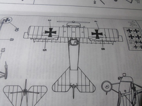
Actually……the correct look of these alierons would be the single wing rib curvature, so I accept it for what it is { I kinda like it better this way anyway}. It’s still confusing, since the decals still point to the F1.
I’m still searching for information concerning this……so far, these modifications were found between the V5 and the F1. If they were visible with the emergence of the Dr 1, they would be seen in the early production. Later productions had the single rib curvatures.
more to come……….
